Welcome to the Remote Setup application. This is step 1 of 2 for the RPS user in setting up assets for vibration analysis with the Remote Setup application in conjunction with the SymphonyAI Industrial (SAII) analyst assistance.
Before you begin, please read the Getting Started page to review the workflow.
Introduction
The mobile application is intended to remotely assist the setup of a SymphonyAI Industrial (SAII) vibration analysis program by providing plant users with an application that walks through the gather of machinery information and delivering it to your SAII setup team.
This section covers the first of two steps in setting up assets in your program.
Gathering Asset Information
- Ensure the mobile application is installed and the initial synchronization is complete. Refer to the Remote Setup Download & Installation page if required.
- Open the RPS app, log in with the credentials provided by SAII, and pull the initial setup if required.
- Synchronize the latest asset information by selecting "Sync" from the menu options.

Note: The SAII Program Administrator will notify the RPS User when the account is ready to proceed with data gathering. Assets are defined in the RPS app by the Program Administrator. - Select the Plant and Area which contains the machine to setup.

- Select an Asset to open the Machine Manager.
-
Photo Captures:
- Photos can be taken for the overall machine, components of the machine, or of the sensors placed on the machine. Photos should clear and easy to identify the machine details. Photos of the nameplate can also be very helpful.
- Select the category to open the camera application to take a photo.
Note: Multiple photos can be taken for the machine, this will impact the amount of time to sync.
- In addition to your camera options (flash, etc.), once captured you can choose between retaking the photo, excepting the capture, or canceling the process. Once captured, you will then be able to rotate, flip, and crop the image as desired.

- A thumbnail of the image will appear in the photos section.
Note: all photos associated with the RPS app can be reviewed from Menu > Photo Folder. - The photo tray can be hidden while gather nameplate and component details by clicking on the chevron icon between the photos section and the component details section.
-
General Information:
- The machine name can be edited if required
- A different area can be assigned if required. Note, new areas can be created by clicking the plus sign in the bottom-right corner to the Area List screen
- Select whether the machine's physical orientation is Horizontal (main shaft is horizontal to plant floor) or Vertical (main shaft is vertical to plant floor).
- Wireless, Portable, Online refers to the intended data acquisition method.
- Asset ID is typically a CMMS ID tag that references this machine.
- Select Foundation type from the pull-down list.
- Select Environment type from the pull-down list.
- Select any of the applicable other details as desired.
- Add Comments to help define other details, operating conditions, etc. about the machine.

-
Nameplate Information:
- Gather as much nameplate information as possible about the machine.
- Note: A photo of the nameplate could be helpful
- Note: If more than one component, such as two pumps, enter both nameplates as best possible. Add a comment if necessary.

-
Component Information:
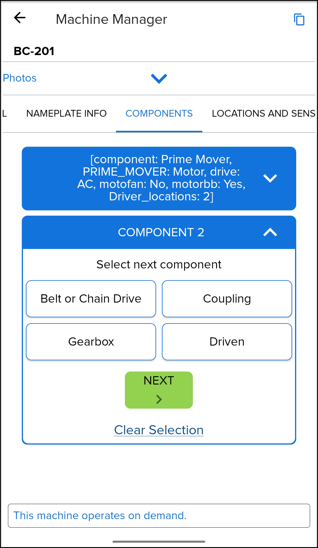
- Asset components can be entered through a step-by-step dialog under the Components section. Components should be entered starting with the driver component (motor, diesel, turbine) and finishing with the driven component (pump, compressor, etc.).
Note: If the Component Selector is not visible, ensure Assisted MID Build is not enabled from the General section.
- Select the first component of the machine by expanding the COMPONENT options.
- Prime Mover: this is a typical driver for most machines.
- Close Coupled Machine: a motor or turbine that does not have a coupling, but rather a driven component extending from the driver shaft. Typically smaller pumps, fans, or compressors.
- Belt or Chain Drive, Coupling, Gearbox, Driven: Select one of these options if the driver is not part of the vibration program such as a turbine that is inside a protected space. Note, that when selecting a starting point for a machine that does not include a prime mover, you will be prompted if a non-monitored prime mover is desired. Adding a non-monitored prime mover would allow diagnostics that may come from such machine as transmitted through sensor installed at other components. Example, motor rotor bar vibration may be present on the pump sensor and the analyst may want to identify this vibration as potentially coming from the motor.
- Once you have made a selection, click the Next button to proceed.
- Step through the questions, answering as best possible until completed the specific component.
-
How many locations are being monitored can be answered as best possible. This may be altered by the SAII analyst when the machine is remotely built in the diagnostic software. The final number of location and their orientation will be sync'd in the final steps. See 4. Sensor Placement & Orientation.
Note: if only installing one sensor or pad on a machine component, you will be asked to indicate the location as either "NDE" or Non-Drive End (the free end of the component) or "DE" or Drive End (the coupled end or location that connects to the adjacent component).
- Select the Next Component in the machine train by clicking the plus symbol and expanding the next Component, such as "Component 2".
-
Belt or Chain Drive:
- Select "Change Speed" to indicate if increaser or reducer and enter sheave diameters and distance between centerlines if available.
-
Coupling:
- Select Flexible, Magnetic, or Rigid as applicable. If other, add a note to the comment at bottom of screen.
-
Gearbox:
- Select number of speed changes in gearbox.
- Single speed change assumes up to four bearing location on the gearbox and up to four positions can be monitored.
- Two speed changes assumes up to six bearing locations on the gearbox and up to four positions can be monitored.
- Multi-speed changes assumes up to eight bearing locations on the gearbox and up to four positions can be monitored.
- The bearing position numbers are relative to the number of possible locations. Bearing positions are generally counted, starting from the driver side and ending at the driven side. Example, given bearings 1 and 2 are the Non-Drive End and Drive End, respectively, or a motor, the next bearing position for a 2-speed gearbox would be bearing number 3. 3 and 4 would be the input shaft, 5 and 6 would be the intermediate shaft, and 7 and 8 would be the output shaft. The next location, say a pump, would be 9 and possibly 10.
- Enter the ratio as best possible. Again, a picture of the nameplate could be helpful.
- Select number of speed changes in gearbox.
-
Driven:
- Select the category or driven component
- Select the type of component
- Repeat the next component selections until you have reached the end of the machine train. Note, the system allows a maximum of 10 components.
-
Clear Selection:
- If an error is made, either redo the component selection or click "Clear Selection" to undo all components and start over.
-
Belt or Chain Drive:
- Asset components can be entered through a step-by-step dialog under the Components section. Components should be entered starting with the driver component (motor, diesel, turbine) and finishing with the driven component (pump, compressor, etc.).
-
Location and Sensors:
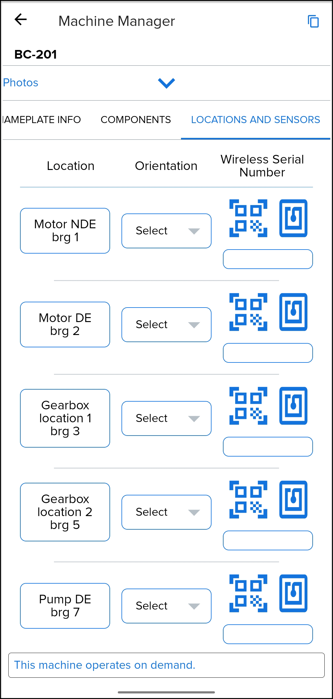
- Location, Orientation, and Wireless Sensor Serial Numbers will be setup in this section. This will be defined by the analyst during the next step. See 4. Sensor Placement & Orientation.

- Location, Orientation, and Wireless Sensor Serial Numbers will be setup in this section. This will be defined by the analyst during the next step. See 4. Sensor Placement & Orientation.
- Sync to finish. Once complete with the asset information gathering, sync your progress to the SAII cloud. It is suggested that this step be done often if lots of high resolution pictures are captured for lots of machines. Once the sync is complete, notify the SAII Program Manager that this step is complete. Next the analyst will use this information and setup the program database.
- Once the database is setup, you will return to the app to finish the setup. See 4. Sensor Placement & Orientation for the next step.
Comments